What is FOCL-VL
The abbreviation FOCL-VL comes from the following combination: Fiber-Optic Communication Lines based on Overhead Power Lines. FOCL-VL are organized by hanging special optical cables on the poles of power lines of various voltages, poles of urban lighting and electric transport networks. The creation of such communication lines became possible due to the fact that the transmission of signals through an optical fiber (OF) is not subject to negative influences from the electromagnetic fields of power lines.
Advantages of FOCL-VL
Compared to lines organized by laying cables in the ground or sewers, FOCL-VL have the following advantages:
the power transmission line infrastructure is very widely developed and covers the entire territory of the country - therefore, there is an extensive base for the creation of FOCL-OHL;for FOCL-overhead lines, unlike underground communication lines, no permission is required to allocate land for laying a cable;the creation of fiber-optic communication lines-overhead lines is faster than the construction of underground lines, since it is not required to carry out complex labor and resource-intensive land works;operation of FOCL-overhead lines is more convenient due to the possibility of visual monitoring of the state of the line;overhead cables are more reliable than underground ones, because the likelihood of damage during excavation is eliminated and the speed of troubleshooting increases (applicable for OPGT).
Many well-known companies, such as Bellcore and Alcoa, cable manufacturers and others, are studying the reliability of fiber-optic lines. Below are tables with data on the reasons for FOCL failure.
Table 1 - Causes of cable communication line failures (according to Bellcore data)
|
Reason |
Cases |
Weight,% |
|
Excavations (for example, in the construction of communications) |
280 |
58.8 |
|
Personnel errors (for example, during operation) |
35 |
7.4 |
|
Rodents |
23 |
4.8 |
|
Cars |
19 |
4.0 |
|
Fires |
15 |
3.2 |
|
Shooting |
13 |
2.7 |
|
Low temperature |
8 |
1,7 |
|
Вода |
7 |
1,5 |
|
Power lines (for example, in contact with phase wires) |
7 |
1.5 |
|
Lightning |
6 |
1,3 |
|
Ice |
5 |
1,1 |
|
Sabotage |
4 |
0.8 |
|
Others |
37 |
7,8 |
|
Unknown |
17 |
3.6 |
|
Total |
476 |
100 |
(Failure - the impossibility of transmitting traffic over the communication line as a result of damage / breakage of the cable. Density - the proportion of the number of failures for a specific reason in the total number of failures for all reasons.)
Table 2 - Fault tolerance of overhead and underground communication lines (according to Bellcore)
|
Air |
Underground |
|
|
% of cases |
9.9% |
90.1% |
|
% cable length |
10.4% |
89.6% |
(% of cases - the share of failures of a certain type of communication lines in the total number of failures of all types of lines.% of cable length - the share of the sum of the lengths of damaged sections of a certain type of communication lines in the total sum of the lengths of damaged sections of all types of lines.)
The main types of FOCL-VL cables
When constructing FOCL-overhead lines, the following types of cables are mainly used: optical cable in a lightning protection cable (OCGT), self-supporting non-metallic optical cable (OKSN), optical cable for winding on a ground wire or phase wire (OKN). About 70% of overhead communication lines in the world are built on the basis of OPGT, the share of OKSN accounts for 25%, and OKN - 5%. At the same time, the regional specificity of the construction of fiber-optic communication lines is clearly expressed: so OCGT prevails in all regions of the world, OCSN is most widespread in America, OKN in England and Scandinavia. When choosing a technology for the construction of FOCL-OHL, it is necessary to take into account the characteristics of the construction region, climatic conditions, terrain, building density, operating voltage and design of power lines, the presence of intersections with engineering structures (power lines, roads, etc.).
OCGT
An optical cable in a lightning protection cable is almost always used in the construction of new power lines or the reconstruction of old ones. This is due to the fact that replacing a ground wire that has not worked out its term is quite an expensive operation. OPGT, in addition to protecting the OF, must also perform the functions of a conventional ground wire - protect phase wires from lightning strikes and provide grounding when short-circuit currents (SC) pass. Therefore, the design of the OCGT ensures high reliability of its operation even on long spans with harsh climatic conditions and a long service life (40-50 years). The scope of OCGT is from 110 KV overhead lines and above, without restrictions on voltage class, and the possibility of organizing complex crossings (the largest crossing in the world, implemented with the help of OCGT, is the crossing over the Mississippi River, where the span was 2.4 km) ... Also, the advantages of OPGT include the possibility of installation at temperatures down to -20 ° C and the highest reliability. However, OCGT is characterized by the highest cost, requires rather complex technological equipment for suspension and installation, as well as significant design costs. Also, if we are talking about the reconstruction of old lines, it is required to turn off the overhead line, which can also be attributed to the disadvantages of OPGT. Due to the highest reliability indicators, it is the OCGT that is recommended for the construction of non-redundant trunk communication lines. Table 3 shows the reasons for line failures with OPGT.
Table 3 - Reasons for failures of lines with OPGT (according to AFL data)
|
Reason |
Number of cases |
Density,% |
|
Lightning |
11 |
26 |
|
Installation defect |
8 |
19 |
|
Shooting |
7 |
17 |
|
Wind |
6 |
14 |
|
Others |
10 |
24 |
|
Total |
42 |
100 |
There are three generations of OPGW, which differ in the design of the core with an optical fiber. Around it is a strand of metal wires (approximate diameter - 2.5 mm and above), which account for the entire load during operation. The wires are made of aluminum clad or zinc coated steel. The first type of wire is preferable, since aluminum is very ductile, has excellent electrical conductivity (higher only in silver and copper) and, most importantly, is a corrosion-resistant material under any aggressive influences. Zinc, on the other hand, is much heavier than aluminum (which is important for suspension) and is inferior to it in conductivity, corrosion resistance and strength (zinc is brittle at any temperature and easily separates from steel). Also, in OPGT, all-aluminum wires are used to increase the conductivity at short-circuit currents (i.e., to reduce the heating of the cable in order to avoid damage to the optical fiber). When using a filament of aluminum and aluminum-clad steel wires, the "life" of OPGW can reach 40 years or more. To meet the requirements of the project for mechanical and electrical parameters, OCGT can have several layers.
Figure 1 - OCGT of the first generation

The first generation of OPGT (Fig. 1) resembles ordinary underground optical cables in terms of the core design - it contains one or several polymer modules with an optical fiber and, in some cases, a central power element (CSE) made of fiberglass. All of these elements are enclosed in an aluminum tube, which protects the core from moisture penetration and improves conductivity. OPGT of the first generation is lightweight and can hold a large amount of OM, but it has a serious drawback - the aluminum tube does not provide sufficient tightness and strength under crushing forces. Such OPGT is still produced by a number of manufacturers, but in general it is gradually being replaced by third-generation cables.
Figure 2 - OCGT of the second generation

In the second generation OPGW (Fig. 2), the problem of crushing strength is solved by using a profiled aluminum core, which also provides high conductivity for short-circuit currents. For tightness, the core is wrapped with aluminum tape. However, this design significantly increases the weight of the cable and limits the number of fibers. Currently, the second generation OPGT is used in projects that are characterized by high short-circuit currents, small dimensions (diameter) and small cable capacitance.
Figure 3 - OCGT of the third generation with a central tube (left) and with a bundle of tubes and wires (right)


Постепенно все большую популярность завоевывает последнее, третье поколение ОКГТ (рис. 3). Главным элементом его конструкции является
a thin central stainless steel tube into which the OV is placed. In its manufacture, the same technologies are used as in the production of needles for medical syringes. Such a tube simultaneously plays the role of a CSE (prevents the occurrence of critical bends), has a high crush resistance and, due to its tightness, prevents the penetration of moisture and corrosive substances. The maximum diameter of the steel tube is 3.8 mm, while the capacity is up to 72 RH. Thus, OPGW of the third generation, with equal mechanical and electrical characteristics with cables of previous generations, often has a smaller diameter, and with equal dimensions - better characteristics. An aluminum tube can be placed over the steel tube to increase conductivity. It is worth noting that in the third generation OPGT, a steel tube can be placed both in the middle of the cable) and in a twist with supporting wires. In the latter case, several tubes can be used, which increases the number of OBs.
OKSN
Optical self-supporting non-metallic cable is used on already constructed lines, when there is no need to change the ground wire, and the terrain allows creating sites for placing tensioning equipment. The main advantages of OCSN include, firstly, its relatively low cost, and secondly, the ability to separate the fiber-optic communication infrastructure from the power transmission line infrastructure (this cable, unlike OCGT and OKN, is not part of the power system). ACSN is suspended on supports either below the phase wires, or along the central axis of the support at the point of zero potential, which is due to the negative effect of the induced potentials of the electromagnetic field on the cable sheath (the so-called dry arc discharge). It is especially pronounced on lines with voltages above 110 kV, when the ACSN shell is rapidly destroyed by a dry arc discharge. For these reasons, the field of use of the OCSN is power lines with a voltage of up to 110 kV with spans of up to 300 m.Application on lines above 110 kV is possible, but economically unprofitable due to the complexity (high accuracy) of the calculation, the high cost of additional supporting elements and shells that protect against electrical influence. It is important to note that the reliable operation of the OCSN can be ensured only by using special fittings for suspending the cable. OKSN is practically the only option for organizing FOCL-overhead lines on lines with a class below 110 kV.
The disadvantages of OKSN include an increase in the load on the supports, the complexity of design, vandalism (mainly shooting and attempts at theft), fires under overhead lines and low reliability. Table 4 shows the reasons for line failures with ACSN.
Table 4 - Reasons for line failures with ACSN (according to AFL data)
|
Reason |
Number of cases |
Density,% |
|
Installation defect |
11 |
38 |
|
Shooting |
8 |
28 |
|
Wind |
5 |
17 |
|
Others |
5 |
17 |
|
Total |
29 |
100 |
Figure 4 - OKSN
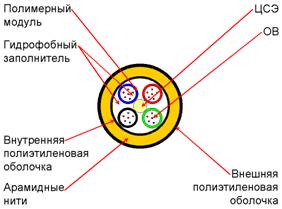
OKSN almost completely repeats the structure of conventional optical cables (OC) for underground installation: CSE, polymer modules with optical fiber, water-blocking tape, polyethylene sheaths of various densities. The main difference between OKSN is the complete absence of metal parts. The metal wire or tape armor is replaced by a layer of aramid threads, which, along with the CSE, are the load-bearing elements of the cable (Fig. 4).
OKN
Optical coiled cable is mounted on already constructed power lines in areas with difficult terrain, which excludes the possibility of using large tensioning systems that require large enough mounting sites. OKN primarily implies a high installation speed. OKN can be wound on a ground wire (OKN-GT, without voltage restrictions) and on a phase wire (OKN-FP, up to 110 kV due to the destruction of the shells by induced currents). The possibility of winding depends only on the condition of the carrier wire / rope (it is recommended to wind it on a new wire / rope or in good condition). The length of the span does not matter, since the OKN is characterized by negligible weight and does not load the load-bearing elements of the power transmission line, incl. supports, and the increase in ice due to such a cable is only 3%.
The OKN design is simple (Fig. 5): power elements (one in the center, several between the modules and the shell), polymer modules with an optical fiber and a polyethylene shell. Sometimes a second, special sheath is added to provide ballistic protection of the cable from hunting shot.
As a rule, the OKN manufacturer develops a unified coiling technology, which includes special coiling machines, coiling machines for winding the line, special couplings and fittings for fastening the cable on supports, as well as other devices to ensure the convenience of the installation process (Fig. 6) and subsequent exploitation.
Figure 5 - OKN

Figure 6 - The process of winding OKN with a special machine (technology of the FOCAS company)

Table 5 shows the basic parameters of the three main types of cable for FOCL-VL. The information provided is rather arbitrary, and when choosing it, attention was paid mainly to the economic efficiency of the project. In Tables 6 and 7, you can get acquainted with the failure rate of FOCL-VL - both general and for different types of cable.
Table 5 - Basic parameters of FOCL-VL cables
|
Parameter |
OCGT |
OKSN |
OK |
|
Power transmission line voltage, kV |
any |
up to 110 |
OKN-GT & ndash; any, OKN-FP & ndash; up to 110 |
|
Maximum span, m |
500 and up |
250 & hellip; .300 |
- |
|
Cable diameter, mm |
11.5 & hellip; 20 |
15 - 20 |
6.2..8.4 (GT) 7.3 & hellip; 9.0 (FP) |
|
Weight, kg / km |
480 & hellip; 750 |
180 & hellip; 360 |
32 & hellip; 69 (GT) 52 & hellip; 77 (FP) |
|
Max working tension, kN |
20 & hellip; 60 |
15 & hellip; 30 |
up to 0.3 |
|
Number of OBs |
up to 300 |
up to 150 |
up to 70 |
|
Resistance to short-circuit currents, kA2s |
180 & hellip; 400 |
- |
- |
|
Max temperature of the ground wire (wire)? С |
200 |
& nbsp; |
260 & hellip; 300 |
|
Working temperature, ° С |
- 60 & hellip; +70 |
- 50 & hellip; +60 |
- 50 & hellip; +60 |
|
Potential of the electric field, kV |
- |
12 & hellip; 25 |
- |
Table 6 - FOCL-VL failure rate (according to Bellcore, AFL and Focas data)
|
10-3/(mile*year ) |
10-3/(km*year) |
|
|
before 1991 |
2.07 ~ 4.39 |
1.29 ~ 2.73 |
|
1991 |
3.21 |
1.99 |
|
1992 |
3.66 |
2.27 |
|
Average |
3.43 |
2.13 |
Table 7 - FOCL-VL failure rate (according to Bellcore, AFL and Focas data)
|
10-3/(миля*год) |
10-3/(км*год) |
|
|
Все кабели |
3,43 |
2,13 |
|
ОКГТ |
0,14 |
0,08 |
|
ОКСН |
0,29 |
0,18 |
(Failure rate = number of failures / (line length * cable life.) Typically, length is 1000 miles (1000 km) and lifetime is 1 year.)
Some other types of cable for FOCL-VL
Among other types of cable that are not as common as those mentioned above, one can distinguish an optical cable in a phase wire (OCP), an optical self-supporting metal cable (OKSM), an optical attached cable (OCP).
OKFP
An optical cable in a phase conductor is generally very similar to an OPGT. The only difference is that when calculating the parameters of the OCP, special attention should be paid to the heating of the cable when current passes through it and the possibility of deterioration of the properties of the optical fiber for this reason. The fact is that the current flows through the OPGW only in two cases: when a lightning discharge enters the cable and when a short-circuit current occurs. But in both events, the passage of current is short enough, so the temperature of the OPGW can reach 200 ° C without harming the OM. For OCPP, the situation is more complicated - the current flows here constantly, the thermal effect is long enough and the OF can gradually deteriorate its characteristics. Therefore, the OCPP must contain a large amount of aluminum.
Figure 7 - OKFP

By its design, the OCPP often resembles a second generation OPGT (Fig. 7): a profiled aluminum core with modules for optical fiber and several strands of wires, among which only a very small part are steel. Because of this, the mechanical strength and bearing capacity of the OCPP are not as great as those of the OGT. On the other hand, the OCPP with a probability of 99% is protected from lightning strikes, but the operation and installation of the OCPP is much more difficult than the OPGT, since it requires the removal of conductive elements from the optical during installation and operation. This technology is mainly used in the construction of new lines that do not require a ground wire.
OCSM
An optical self-supporting metal cable is an analogue of OKSN. In general, OCSM has the same features as OCSN, application features, advantages and disadvantages. But OKSM has its own rather negative nuance - the metal elements used in the composition, which make the cable heavier and create the danger of a negative impact on it from the power line currents. However, OKSM can be used on longer spans than OKSN, due to the greater mechanical strength of the metal bearing parts.
Figure 8 - OKSM

OCSM often has the form of a "figure eight" (Fig. 8): a core made of CSE and modules with an optical fiber and a separate metal carrying cable, enclosed in a single sheath.
OKP
An Optical Attached Cable is an OK having the same application guidelines and design as an OKN. OKP is distinguished by other methods of installation: most often such a cable is either attached to the supporting element with a cable, or attached with special brackets. It should be noted that the installation of OKP is not always convenient, since the installation of brackets takes longer than winding and requires more complex equipment, and winding with a cable causes an increase in the load on the supporting structures. In addition, there is the possibility of such a cable breaking after a lightning strike due to damage to the fasteners. However, in the case of attaching the OKP with staples to a wire or cable, there are no laying machines moving along them, and the assembly load on the supporting elements is reduced.
The choice of technology (cable) FOCL-VL
There are many details that speak in favor of choosing one or another type of cable for creating FOCL-OHL, therefore it is very difficult to develop a unified system for choosing a technology. However, focusing on the long-term international experience of completed projects, the convenience of equipment installation and the economic efficiency of construction, a decision can be made in favor of any cable based on the algorithm shown in Fig. nine.
Of course, the monetary cost of construction is an important factor when choosing a cable. However, for different projects, the cost of the same type of cable can vary significantly, which is due to the difference in climatic conditions, terrain, condition of overhead lines, etc. In the most general sense, the cost of various types of cable can be estimated as follows (by reduction): OPGT - OKSN - OKN.
Comparing various technologies for creating fiber-optic communication lines, one can unequivocally state that the best of them in terms of reliability and durability is the OPGT technology. Such a cable has a lifespan of 40-50 years (versus 25 years for other types) and is able to withstand any negative external influences. However, we often have an overhead line without a ground wire, in such cases, the technology of OKSN or OKN is irreplaceable. Thus, the construction of a branched network based on FOCL-overhead lines is associated with the use of various technologies, where the main line is mostly OPGT, with transitions to OKSN or OKN when organizing branches, there are also cases when it is necessary to switch from overhead lines to underground cables and vice versa. It is worth noting that for the organization of branches on lines up to 35 kV, a self-supporting insulated wire (SIP) with built-in OF is often used recently.
Figure 9 - Algorithm for choosing a FOCL-VL cable

For energy companies that are building a new transmission line or are going to reconstruct the old one in the coming years, creating on its basis the main FOCL-VL, OCGT is the most optimal solution. Firstly, the advantages listed above of this type of cable speak in its favor. Secondly, as a rule, the main transmission lines have a voltage of 220 kV and higher, which excludes the possibility of using OKSN and OKN-FP. And thirdly, the reconstruction or new construction in one way or another provides for the suspension of a new ground wire - therefore, it is easier to immediately use OPGT than to hang up a conventional cable and wind OKN-GT.
Market of cable manufacturers for FOCL-VL
The market of OC manufacturers for FOCL-OHL includes a fairly large number of companies. Three of the largest stand out among them: AFL Telecommunications (USA / Japan) - 24% of the total amount of overhead cable installed in the world, Prysmian (Italy) - 13%, and Alcatel (Germany) - 13%. The share of each of the other companies in the world base of created FOCL-VL does not exceed 9%. AFL Telecommunications is the telecommunications arm of AFL, a joint venture between ALCOA (USA, aluminum industry) and Fujikura (Japan, fiber optic industry). AFL Telecommunications is the heir to FOCAS, one of the first creators of fiber-optic cable, which was later taken over by AFL. Prysmian is the former cable division of the large Pirelli company, which recently took over and is now an independent manufacturer specializing exclusively in the production of OK and accessories, incl. for FOCL-VL. Alcatel operates exclusively in the telecommunications industry and produces a wide range of equipment: from mobile phones and PBXs to airborne OKs and accessories.
Most of the large Russian OK manufacturers close to Kazakhstan - Samara Optical Cable Company (Samara), Sevkabel-Optic (St. Petersburg), OFS Svyazstroy-1 (Voronezh) and others - produce FOCL-VL from all types of cable only OKSN. Attempts by SOKK and SKK to organize the production of OPGT on the line for the production of conventional armored underground cable ended in failure due to the poor quality of such a cable. The only exception is the company "Saranskkabel-Optics" (Saransk), which four years ago purchased a completely specialized line for the creation of OCGT and annually produces up to 3000 kilometers of such a cable that meets all international quality standards.
In Kazakhstan, where the development of the FOCL-OHL market began approximately in the mid-90s, the leading positions today belong to "Prysmian". However, the volume of installed air control systems in the republic is very insignificant (especially in comparison with Western countries and Russia), therefore, the position of "Prysmian" in our country cannot be called sufficiently strong. Today in Kazakhstan there is an intensive development of the optical communication industry, incl. on the basis of energy facilities, as a result of which the country became the object of attention of other leading manufacturers of equipment for FOCL-OTL, in particular "AFL Telecommunications" and "Saranskkabel-Optics". The products of these companies have been promoted to the republican market for the last two or three years, and already at the moment they are seriously competing with Prysmian, which is confirmed by the gradually growing interest of local customers and specialists in AFL and SarkO cables. It is important to note the fact that, in essence, OCGTs of the same generation from different manufacturers, if they are designed for a specific project, are identical and can be interchangeable. In other words, a cable from Prysmian with a diameter of 11 mm can be docked with an AFL or Nexans cable with a diameter of 11 mm, etc., which allows the customer to have a competitive environment in the construction of fiber-optic communication lines, and not to depend on one manufacturer.
FOCL-VL design
As mentioned at the beginning of the article, the design of FOCL-OHL is a rather complex process that requires careful analysis and repeated verification of the correctness of all design data. This is mainly due to the fact that it is necessary to maintain a high degree of reliability of the air control system. Such a cable, of course, is much less likely to be damaged than an underground one, however, damage to the OC in the ground is most often of an accidental nature (excavations, etc.), while the negative impact on the suspended OC is constant and systematic.
One of the main components of the FOCL-OHL design stage is the collection of initial data. These most often include: climatic conditions (thickness and density of ice, wind pressure, maximum, minimum and average annual temperatures, frequency of occurrence and power of lightning discharges), terrain, condition of power lines (condition of wires and cables, characteristics of supports, magnitude of short-circuit currents) , description of the power transmission line route (intersections with rivers, roads and other engineering structures). To obtain such information, not only work with the existing documentation is required, but also a pre-design survey of the future line. In addition, the initial project data includes information from the technical assignment for the project related to the number and type of optical fiber, the FOCL route plan, etc.
The further course of the design is the joint work of the design organization, the equipment manufacturer (or his representative), the customer and the contractor to develop a single ready-made design solution that suits all parties and meets all the standards and requirements. At the stage of project development (especially for already existing power lines), the main problem is to develop a product (cable) that simultaneously meets all the requirements for the amount of OM and their normal functioning, for maintaining the normal operation of existing facilities, for resistance to environmental influences , electromagnetic fields of power lines and short-circuit currents, for ease of installation, etc. Often these requirements are mutually exclusive (what is the complexity of the design), which forces all interested parties to develop and analyze many different options for creating FOCL-OHL using different types and designs of cable and its accessories.
It should be noted that when designing fiber-optic communication lines-overhead lines, the main documents are the documents regulating the norms for the creation and operation of energy facilities, and not telecommunications. These include, first of all, "Rules and Norms for Electrical Installations", as well as other regulatory documents. But at the same time, you should also refer to the recommendations issued by the manufacturers of cables and equipment for their installation and operation.
Construction of FOCL-VL
The method of pulling, or pulling, OK is the only one that is recommended to carry out the suspension and installation of cables such as OKGT and OKSN (Fig. 10). In accordance with it, at one end of the installation section (5-6 km), a brake machine and a drum with OPGT or ACSN are installed at the anchor support, at the other end - a tension machine. Those. it is required to create two small mounting pads, and not to go through the entire anchor section. On all supports of the site, rolling rollers are hung, through which the leader-cable is passed. One end of it is attached to the tensioning machine, the other to the OK. Before this, several turns of OK are passed through the drum of the brake machine. After that, cable laying begins: the tensioning machine winds the cable leader, simultaneously pulling the OK through the rolling rollers along the entire length of the section, and the brake machine slows down the OK broach and pulls it, thereby creating the necessary tension. After full broaching of the OK along the site, the tension clamps are mounted on the anchor supports without loosening by the tension machines, then the cable is transferred from the rollers to the supporting clamps, vibration dampers are mounted, the cable construction lengths are connected in the couplings, the construction stock OK is laid on the supports, etc.
Figure 10 - Scheme of construction of FOCL-VL with OPGT or OKSN

Installation of FOCL-VL with OKN cable (for both GT and FP) is performed using special equipment supplied by the OKN manufacturer (coiling machine with a set of auxiliary equipment). Thus, the manufacturing company not only supplies the OC, but also provides the technology for the suspension and installation of the OC. This somewhat narrows the scope of the OKN, however, it gives guarantees for the installed FOCL-VL complex. As a rule, OCGT and OKSN manufacturers are responsible only for the delivered OK. The mounting equipment for the OKN suspension is small and allows for a high installation speed, continuous operation without stress relief (for OKN GT). The OKN suspension technology is an ideal method for carrying out installation work during OKN crossings through water barriers, city blocks and other similar objects, as well as in remote and mountainous areas. At the same time, it is not required to erect special structures at the intersection of fiber-optic lines-overhead lines of roads or railways. Application of the OKN suspension method makes it possible to build FOCL-OHL with an average laying speed of up to 4 km of cable per shift. The speed of cable laying is influenced by many factors, primarily the ability to disconnect lines, the number of crossings, weather conditions and terrain. For an approximate calculation of the construction speed, one can proceed from the data given in Table 6.
Table 8 does not take into account the loss of time for receiving outages, organizing intersections, weather conditions, downtime, etc. From our experience in construction, the speed of laying the OCGT is 40-50 km per month by one construction team, subject to well-organized work on disconnecting the overhead lines.
Table 8 - Approximate speed of OK installation by 1 team per day.
|
Parameter |
OCGT |
OKSN |
WINDOWS |
|
Trail preparation days |
2 days. |
2 days. |
1 day. |
|
Pulling per day |
5 km. |
5 km. |
4 km. |
|
Editing per day |
5 km. |
5 km. |
- |
|
Total mounted on average per day for 1 brigade |
2.5 km. |
2.5 km. |
4 km. |
It is difficult to accurately calculate the cost of the future FOCL-OHL even at the design stage. However, Table 9 still presents the results of assessing the costs of building FOCL-OHL based on various technologies. All the figures given below are rather arbitrary, and one should not compare with them the real costs for specific projects. They reflect only the trends in the ratio of costs between different technologies and give a general idea of the financial side of the issue. For a more accurate assessment of the used FOCL-OHL technology from a financial point of view, it is also necessary to take into account future operating costs. At the planning stage of FOCL-OHL, at least an approximate estimate of the costs of its operation is required. To make a choice between FOCL-OHL technologies, based only on the cost of OK-OHL, would probably be wrong. The figures given in Table 9 do not take into account the costs, which, strictly speaking, must also be taken into account when planning and designing FOCL-OHL. These are the costs and losses incurred by the power system in connection with the shutdown of the overhead line during the work, as well as losses due to damage to crops under the overhead line, etc.
Table 9 - Costs for the construction of FOCL-VL
|
Name |
Type |
OKSN |
OCGT |
OKN |
|
|
OK |
m |
4,200 |
5 400 |
3 800 |
|
|
Armature |
m |
1 600 |
1 280 |
1,500 |
|
|
Couplings |
m |
160 |
240 |
250 |
|
|
Non-standard (fasteners) |
m |
600 |
200 |
200 |
|
|
Track selection |
P |
600 |
600 |
600 |
|
|
Line Inspection |
P |
840 |
840 |
840 |
|
|
Design |
P |
1 200 |
1 200 |
1 200 |
|
|
CMP |
P |
5 560 |
5 560 |
10 560 |
|
|
Overhead line admission |
P |
300 |
300 |
300 |
|
|
Losses |
P |
250 |
250 |
250 |
|
|
Restoration of supports (1 support per 10 km) |
P |
2,000 |
0 |
0 |
|
|
Total |
17 310 |
15 870 |
19,500 |
||
It is worth adding the costs of one of the non-core technologies of FOCL-VL - OKFP: the cable and work are comparable in price to the OKSN, however, fittings, couplings and fasteners from the design complexities associated with grounding and insulation of live parts are quite expensive - about 1.5- 2 times higher than that of OCGT and OKSN. As a result, the total costs for FOCL-OCPF are approximately 19,000.
Accessories for FOCL-VL
Air OK accessories include suspension fittings and couplings. The nomenclature of accessories for the OK suspension is very extensive, it includes: tension and suspension clamps, clamps for cable running along the support, vibration dampers, as well as their component parts (thimbles, lanyards, staples, etc.). By design, the fittings are divided into two types: bolted and spiral. Bolted reinforcement (Fig. 11) is, as it were, part of the support where it is mounted, and provides a higher strength of the OK termination, however, it is most often used for temporary cable tension during installation, since long-term operation of bolted clamps on the OK can lead to its damage.
Figure 11 - Bolt tension clamp

For permanent operation of OPGT or OKSN, spiral reinforcement is used (Fig. 12), which is already a part of the OK itself. The spiral devices handle the cable more "gently" due to the distribution of the load inside the clamp over the entire area of the OK, which excludes the point impact on the cable sections and their damage (as in bolt clamps). In addition, spiral fittings are mounted much faster than bolted ones and do not require the use of special tools for this.
Rice. 12 - Spiral supporting clamp

For OKSN and OKSM, installed on low voltage lines (10 kV) and with short spans (40-70 m), the automatic cable fixing clamps produced by the Delfos and Telenco companies are excellent (Fig. 13).
Rice. 13 - Auto-fixing clamps

The main requirements for couplings for air OC are reliability and tightness of the coupling, convenient and safe location of the OV in it, convenient and quick installation of the coupling on a support, the ability to store a stock of OV and OC lengths in the coupling or next to it. For OPGT, it is recommended to use metal couplings, and for OXN, plastic couplings. The main problems for couplings placed on power transmission line poles are protection against shots and insufficient tightness, for the solution of which it is necessary to use special armored caps (especially for plastic couplings) and special sealing gels or heat-shrinkable components. However, today most of the world's manufacturers offer their customers couplings that fully meet the above requirements and do not have problems with tightness and strength (Fig. 14).
Fig. 14 - Metal sleeve for OPGT or OKSN
Emergency recovery work on FOCL-VL.
Emergency recovery work (AVR) on FOCL-OHL is carried out, as well as on other FOCL, with the use of emergency recovery teams. The restoration of communication is carried out using a cable insert, which is a temporary solution, then permission to repair the line is obtained and repairs are made. It should be noted that OCGT changes in building lengths. The standards for ATS are given in Table 10. It is important that for the operative maintenance of the route with the OKN, the constant presence of a winding machine is required, which leads to a significantly high cost of work. Otherwise, the speed of elimination of accidents sharply decreases.
Table 10 - Standards for ATS
|
Cable type |
Time for elimination of the accident (no more) |
|
| & nbsp; |
Down the drain |
In the ground / suspended |
|
08-fiber |
6 hours |
18/8 hours |
|
12-fiber |
6 hours |
18/8 hours |
|
16-fiber |
6 hours |
18/8 hours |
|
24-fiber |
8 hours |
24/12 hours |
|
32 fiber |
10 hours |
24/14 hours |
|
48 fiber |
14 hours |
24/16 hours |
|
96-fiber |
20 hours |
28/24 hours |
Conclusion
Summing up, we can safely say that in Kazakhstan it is necessary to actively develop FOCL-OHL, and this primarily concerns not telecommunications operators, but the owners of transmission lines. A company that decides to build such a communication line, with relatively low time and capital costs, will receive a reliable modern telecommunication system that is able to satisfy the owner's internal needs for information exchange and gives him the opportunity to become a full-fledged player in the local telecommunications market: to lease OV and channels data transmission, become part of national and international communication networks, etc. The economic effect will also be received by design organizations and construction companies that have mastered the methods of calculating and installing FOCL-overhead lines.
Literature
A.V. Shmalko, N.K. Sabinin. FOCL on overhead power lines. // VKSS. Connect! - 2001V.V. Novichkov, N.K. Sabinin. Choosing an optical ground wire. // Lightwave Russian Edition. - No. 3. - 2004S. Lisle. The history, prevention and impact of fiber optic cable failures. // Bellcore. - 1993D. Crawford. Fiber optic cable dig-ups - causes and cures. // NRC. - 1993S. Clift. Statement of technical conformance: aerial cables reliability. // Focas. - 1996J. Chamberlain, J. Patton. Optimizing Fiber Optic Cable Availability. // Norscan. - 1998J. Healy. Fixing facility damages: sharpening the focus on prevention. // Telcordia. - 2000Internal data on reliability of Optical Groundwire and All Dielectric Self Supporting fiber optic cables. // Alcoa Fujikura Ltd. - 2001
You will find complete information about cables for FOCL-OTL in the corresponding section of our website.